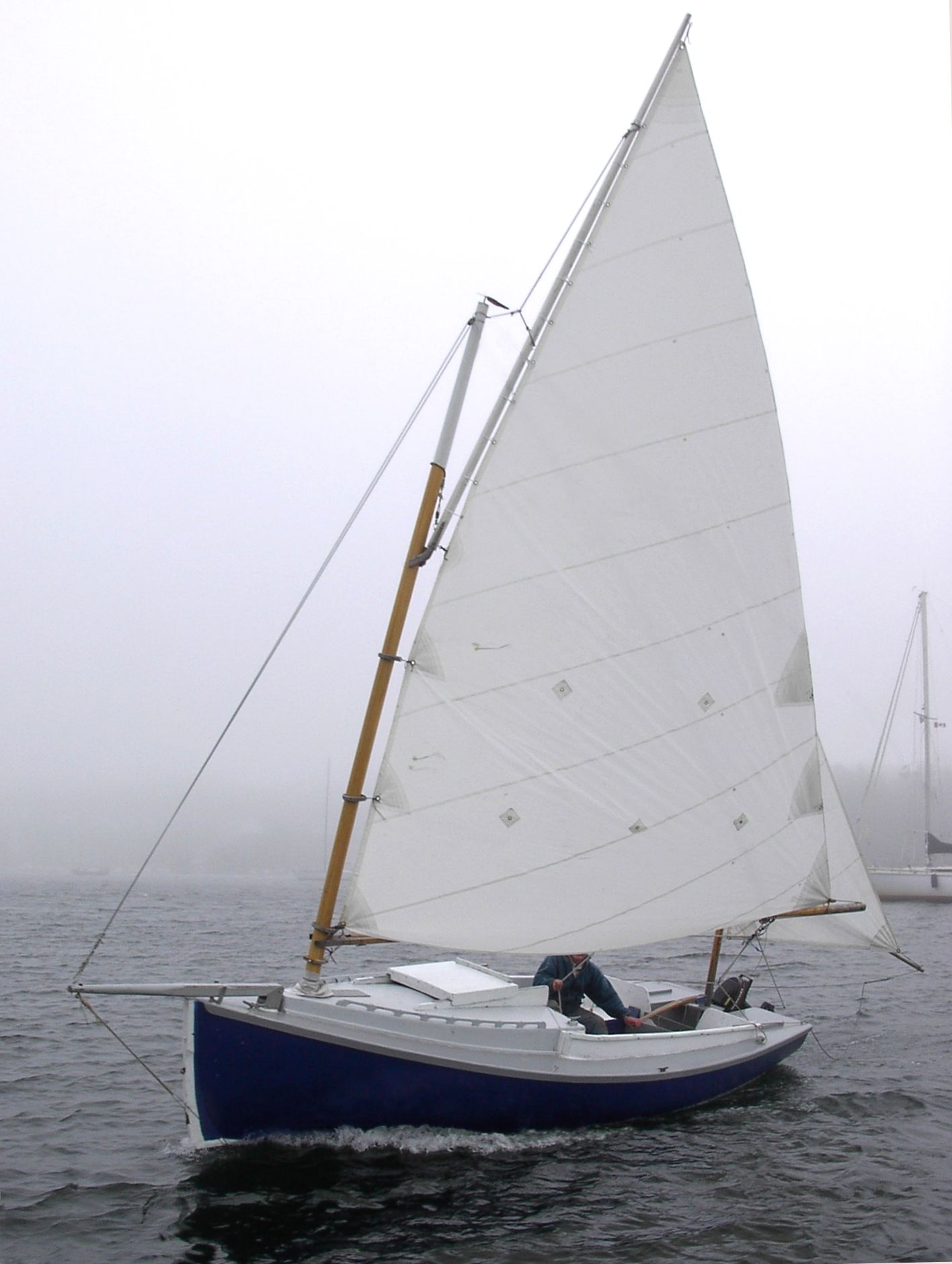
Tuesday, January 28, 2025

A more attainable build - 10 foot Chaisson Semi-Dory

I noticed that the hull lines of Welsford's Penguin are quite similar to those of the Chaisson semi-dory. They both use 5 lapstrake laps per side to simulate a rounded hull and other than the tumblehome near the transom of Welsford's Pengion, the general shape is very much the same. I wonder if because John Welsford began designing smaller boats and has gradually added larger boats to his fleet of designs - that perhaps his larger designs are in some way derived from smaller simpler boats like this semi dory? Penguin's hull certainly looks to my eye like an enlarged version of a row boat.

The Chaisson semi-dory is a round sided flat bottomed row boat that was made by the Nova Scotian born Chaisson brothers down in Swampscott Massachusetts over a hundred years ago. It was produced in lengths varying from about 10 to at least 14 feet long and made with lapped riveted planking to various grades of finish. It would have likely been sold for use as a tender that would have been towed behind a bigger cruising boat. In a book I have by John Garden who was a US wooden boat builder with a wide knowledge of dories, I found the lines and offsets for the 12 foot version and it was Garden who shed some light on the history of this boat.

I have been thinking about making a break-apart nesting tender for our current sailboat for a while and think that one about 10 feet long would make a wonderful row boat and could be stored on deck if split into say a 6 foot and a 4 foot section (or 5.5 and 4.5 feet perhaps). The smaller section would fit inside the larger and would not take up as much deck space as an 8 foot tender. Each section would float independently and be bolted together in the water. I could build the boat using similar stitch and glue techniques to what would be used to build the bigger sailboat too. 

The cost and time involved would manageable - 3 or 4 sheets of 1/4 inch marine plywood and a few lengths of fir or spruce for the gunwales and thwarts (seats). Plus a gallon of epoxy and a few yards of fiberglass cloth. Based on the Devlin Egret I built back in the 1990's I would think this could be done in a few weeks of full time work with maybe another week to do a splitting/nesting version. She would be built upside down on a ladder frame and would only need a spreader or two to push her out to the right shape before glassing her, although if I build a nesting version, I would put a double bulkhead at the appropriate place that would act as a mold and could then be sawn through to produce the two boat sections.

Free!Ship screen showing lines and developability check
 

I used the same software - Free!Ship to design the dory. I loosely based the lines on those shown in Garden's book but adapted it for 3 panels instead of 5. I then printed off the plates and used these as templates for wood planking. However the wood proved a bit thick to bend into shape with this smaller model so I switched to a Corn Flakes box to make a simple model.

Lines Plan - Not sure where that diagonal line at the bottom left is coming from!

One thing I have learned is not to trust the transom plate development by Free!Ship. Both on my 22 foot model and on this one, the transom is much too short to work. Here are some pictures of the cardboard model with a piece added onto the transom to bring it to the correct height.

Model without skeg attached (skeg will be needed for directional stability)

Top view showing one thwart. There will be forward and aft thwarts as well

And my six footer added for scale. Skeg is visible at bottom right.

Sunday, January 19, 2025

Boat model planked up

1:12 scale model with 1:12 scale 6 footer sitting in what will be the galley area

I have learned a few things from making the model. I have a human scale (1:12) fi gure about the equivalent of a six footer that my Grandmother knitted for me when I was a kid back in the 1970s. It is a 'Dad's Army' type character - my Grandfather was in the Home Guard in the UK during WW II - and can be posed because it has a skeleton made of pipe cleaners. Using this manikin I quickly determined that a mocked up galley 2 feet deep would leave no room to stand in front of it, so I shrunk the galley width to 18 inches. I also noted that the passageway on the other side of the main cabin was a bit narrow, so I shrunk the bunk/settee a couple of inches. Finally and most importantly a 2 foot wide toilet with solid bulkheads either side looks like a really tight squeeze so in the design I shifted the aft bulkhead 4 inches back to give some more room for my larger potentially claustrophobic guests.


The other purpose of the model was to see how the hull planks would fit to each other and conform to the bulkheads (they should all join together without gaps). I was also worried that there would be too much twist needed at the very front in the lowest panel. The twist does appear to be an issue true as I had to torture the thin sheet of basswood so I think this plank or at least the first section of it would have to be made of 2 layers of 1/4 inch plywood. 


You can see here where I experimented with joining planks. I used a simple butt joint backed up by a butt block inside.


The planking does sort of fit but not exactly. The planks fit fairly well to each other but not as well to some of the bulkheads. They also come up too high at the transom. Part of the problem is probably that when I built the bottom I did not put enough curvature in it because it sprang back to a flatter shape when I took it off the strongback after building it upside down. Still, I think the transom angle and match between planking height and transom are off and I need to figure out what caused this. It could be an error in the CAD software or more likely a mistake I made.

I also scaled down the bulkheads using the design software by a percentage where I should probably have taken the time to draw them out as the CAD software projected them and then subtracted the plank width before marking them out. Finally, I did not place the bulkheads with enough exactness fore and aft so the planks do not lay fairly against a couple of the bulkheads.

I think though that despite these issues, the over-all design could work when built in full scale. I would build the whole thing upright to ensure the bottom curvature is correct and turn the boat over only after it was all planked up to add the keel at that point. I would also template the planks before I cut them out to check that the designed versions would exactly fit the bulkheads as laid out. Finally, I would be more careful in reducing the bulkhead's dimensions to allow for plank thickness.

Working with the model has been a bit frustrating. The basswood is light and forgiving but breaks easily across the grain and the lighter bulkheads were patched together many times during building. My full size tools (circular table saw and oscillating multi tool) are pretty heavy handed and cutting fine shapes in 1/16 thick wood is tricky. I managed to take a chunk out of one of my fingers using the table saw for this purpose. Ideally I would use a Dremel type tool and sharp exacto knife for this work.

I am now not so sure I will proceed with building the actual boat. Rani has made it clear that long trips on a 22 foot sailboat are not her idea of a perfect holiday. So, I must weigh the fact that what I will be doing will be a fun creative project against the likelihood that I will be sailing it on my own and might need to keep a second larger boat at the same time if I want to cruise with my wife! After reading more account of home builders creating similar boats, I have also re-estimated the time to build upwards to a (hopefully worst case) time of 4000 hours/4 years. At least this has been a great learning process even if I never get to sail in a boat I designed and built...

When I carry on with the model, I will build the cockpit seats and floor and then fit out the galley and settees.


Wednesday, January 15, 2025

Bird watching and testing out a lens for Tanzania

We are off for a safari and visit to Tanzania next month and my brother has generously agreed to lend me some fancy camera equipment for this trip. I took the ferry over to Vancouver yesterday and he picked me up and took me to the Reifel Migratory Bird Sanctuary in nearby Delta. I fitted a 70-200 lens with a 2X teleconverter to the Canon EOS 5 body that Mike had given us years ago for use in Nepal and elsewhere. The lens is one of Canon's high end pieces of glass with a large aperture and even with a teleconverter (which dims the image a bit) it still took pretty decent pictures of various birds. Below are some results. I was pretty happy with them given I have almost no experience shooting birds. Good equipment makes it possible to get a few good shots out of dozens of attempts.

I believe this is a ring necked duck in company with a female mallard

Northern Pintail duck

Sandhill Cranes visit the sanctuary

Another Pintail

Northern Shoveller

American Wigeon

Hooded Merganser

There were sometimes over a dozen blue herons hunched over keeping each other company

This short eared owl was just one of at least 3 who were hunting voles in the salt marshes. They are active during the later day unlike many owls who only hunt when it is darker

My brother was not alone in his passion to capture wildlife. Lots of other birders were out on this relatively warm and occasionally sunny January 14.

Wood duck

This tiny Saw whet owl was asleep the first two times we walked by his tree. On the third visit he/she had just opened its eyes.


Wednesday, January 8, 2025

Centerboard and Case

The centerboard shape evolved a little as I drew it out at 1:12 scale and then made one out of an old cedar shingle offcut that happened to taper about  the right amount from top to bottom anyway. As a bonus, the aromatic red cedar smelled nice as I cut and sanded the model centerboard to a rough NACA 0010 profile.

I also spent a bit of time making a spreadsheet to help calculate how much lead I would need to make sure my centerboard goes down properly. Cedar with fiberglass over it weighs a lot less than the equivalent volume of water, so needs ballast added to sink it. I worked out the volume of the centerboard by approximating the cross sectional area at top and bottom using the same method (since they have the same proportions of width to thickness) and then used the average to work out the volume. It was then a matter of comparing the weight of fiberglassed cedar to water and adding a suitable volume of lead. It worked out that if I replace the bottom 3.5 inches of the board with a lead casting that the board should sink. Alternatively I can build a cavity of a suitable size into the board and fill it with lead.


Centerboard Details - There are 2 more even more detailed pages of sketches showing how the centerboard case goes together and how the pin the board swings on is made


The next details to work out regarding the board and case were the overall structure. How I will take the board our from inside the boat, and how to make the pin, which the board will pivot on. The latter will be below the waterline so must be carefully made and water tight. It took me a couple of days of part time research and design to sort all this out. There is a wealth of material out there in particular on BoatDesign forums at boatdesign.net.

I made the case from basswood with ripped strips of spruce to simulate the douglas fir structure holding it together. When I went to fit it into the boat today, the slot I had cut a few days ago was in the wrong place because I have had to shorten the boat by about 3 inches to ensure the longest planks will come out of scarfed 1/2 inch plywood. I also shortened the board slot a bit by putting a notch at the forward end of the board.

Bottom with centerboard case in place. White stuff is patch repair to fill in gaps

Centerboard shown fully lowered

I have been reading up on stitch and glue construction, which is the method that I intend to use to make the hull. This uses wire and small holes drilled in pairs of sheets of plywood that will be joined together to make the hull. It differs form the method that Welsford suggests to build Penguin and I have realized that I will need to use thicker plywood than if I had built Penguin. So the hull panels and bulkheads will end up being 1/2" instead of 3/8" as I had initially thought. This means that I will be better off using proper 1:8 scarfs them rather than using fiberglass butt scarfs as I had intended. Hence I need more plywood for this as each scarf takes up 4 inches, so I was forced to shorten the boat.

I have begun work on the bulkheads that will support the planking, deck, and cabin. They are defined by offsets that can be output from the boat design software (FreeShip) I am using. You specify where along the length of your boat you want to make each 'slice' through the hull and the program will figure out the shape at this point. This is defined as a set of XYZ coordinates. I used a simple text processing script to remove un-needed points and to define both halves of the boat in one go so that I can have Google sheets graph these numbers. I also had to adjust these offsets for the planking thickness I will use because the coordinates are to the outside of the hull and I need the shape of the inside of the hull. I did this by resizing the boat by the appropriate amounts and regenerating the coordinates of each bulkhead. Once I have  graph, I will print this out at 1:12 scale.

Next steps will be to add detail to each bulkhead so that in addition to being the right overall shape it also supports the various seats, floors, and other furniture we need as well as allowing access into and within the boat. I must also determine each bulkhead and stringer's thickness and material. Once this is done, I will model all the bulkheads in basswood and spruce and set them up on top of the bottom making ready for planking the boat,

Sunday, January 5, 2025

Keel modeled and then redesigned, reverting to better centerboard shape

I was not happy with the long parallel sided keel with tapered ends. All my reading says that a foil shape will have less turbulence and more lift and while this may be a very minor issue in a small low performance boat, I think you might as well do something right or at least do a cost/benefit analysis to see if it is worth the extra effort. So I started looking at how one could make the lead casting and deadwood keel assume a NACA foil shape. Because it is very long and thin, a lower number 4 digit series foil would be the best choice. 

I chose a NACA 0006 foil with a maximum span of 6% of its length for the shoe keel. This resulted in a foil that is a bit fatter than the 8" wide parallel design in the last post. For the model, I built this using wood alone (as I did not have any lead or other suitable metal at hand) and attached a skeg using separate pieces of wood as well as shimming up the keel to allow for the curvature of the bottom. In the real boat, I would cast the lead in a plaster or wood mold made to the foil shape with rounded edges and a forward section that also curved up to the boat. The rest of the wood skeg would be made of laminated fir and/or plywood, glued up with epoxy and well sealed with epoxy and fiberglass. It would all be fastened to the boat with stainless steel bolts or rod and stainless steel screws as well as epoxy and fiberglass.

The other change I made was to revert to a tapered centerboard similar to my first design but a little bit longer. This helps reduce the bulk of the case in the cabin and makes for a more efficient underwater shape. I figured out that the complexity I was concerned with could be dealt with by making a series of plywood templates in decreasing cord (length) and width that a router would ride on to cut the changing profile. A straight board would required only two plywood templates of the same profile so this is a bit more work, but not ridiculous considering its double benefit. 

 Following is a sketch of the proposed modified keel and board. Note that it is different from what I built in the model, which used a fatter full NACA 0006 profile (see photos below). Once I completed the model I realized that the NACA 0006 profile was wider than it needed to be and fatter further forward. This would cause more surface friction than necessary, so I flattened the sides of the foil such that I still have enough lead to ballast the boat. The purple shaded area is lead and the green is laminated wood. I had to increase the depth of the foil to 3.5 inches from the 3 inch deep wider foil so as to have enough ballast.

Hopefully this is the final design! I took offsets (distance from a baseline) along the length of the keel that will be laid out on wood to get the curvy shape of the keel when building the real thing.


Model with keel and deadwood added. Note these are a bit deeper and wider than the final plan as I made modifications to the plan once I saw the model

Added some fairing compound.

I will likely paint the bottom next if I don't end up tearing off the keel and building a new one based on the latest plans.

Next steps are to build the centerboard and case. I will then remove the bottom from the strongback and re-do the strongback supports to support the bottom and keel turned rightside-up.


Thursday, January 2, 2025

Keel, skeg, lead ballast, and centerboard

When a sailboat when moves through the water driven by the wind, the forces on the sails are balanced by the water pushing in the opposite direction against the keel, the centerboard, and any other part of the boat that is underwater. If the shape and positions of these underwater pieces are not well thought out then the sailboat will be difficult to steer or will slide sideways (make leeway) more than is necessary when sailing towards the wind. Other possibilities are that the boat will try to turn away from the wind if you let go of the tiller (called 'lee helm') - an undesirable trait because things can get out of control if this happens rather than turning up into the wind and coming to a halt.

I already mentioned balancing the keel position against that of the sails in an earlier post, but the overall profile of the centerboard and keel and the position and weight of the ballast also need to be worked out. How thick should the centerboard be to handle the strain when sailing to windward in a 30 knot breeze? How deep and wide should it be? What shape should it be - a foil like an airplane wing perhaps or is a flat plate ok? Should it be straight up and down or at an angle? These questions have been answered by researchers and of course much of this research has been around improving performance in racing boats.


An attempt at keel, ballast, and centerboard

The centerboard design I illustrated in an earlier post was based on my initial research and was different from Welsford's Penguin, which has a straight board. My design has the advantage of fitting better into the boat and leaving a lower trunk and more space near the companionway. The problem is that if I want to shape a centerboard that changes its width (cord) from top to bottom, the profile shape has to change continuously. This is a problem, because I intend to use a NACA foil section (like an airplane wing) to make the board efficient as possible. If I then try to make a board out of glued up strips of wood, I will want to use a router or some sort of other power tool to shape this. This will tricky because one would need a half dozen templates and interpolate in between them to do the shaping. It would be far easier to make a simple jig like this person has that follows one profile. 

The other downside to my design is that because it tapers, it has a bit less area than a straight board. I am already proposing to use less than the recommended keel area versus sail area (the rule of thumb being about 3.5% or say 10 sq feet). So I have redesigned the board to be 2 feet wide all the way along and chosen a NACA 0010 section, which has a maximum thckness of 10% of its cord or width. Hence the board will be 24 inches wide by 2.4 inches thick at its thickest. The board will give me 8 sq ft of area and the keel and skeg will provide plenty of additional underwater profile.

Here is the latest attempt at a centerboard and keel.


Building the model and doing these drawings has helped me think through construction and hopefully avoid doing something that will be costly or difficult with the full sized boat. Drawing out the profile of the skeg and ballast section allowed me to work out the ballast placement and knowing the centerboard width was necessary to determine the size of slot that must be cast in the ballast and allowed for in the wood that supports the ballast. This slot affects ballast calculations too.

Balancing the location of the ballast fore and aft of the center of lateral resistance (CLR) is only a guess and in a small boat the weight and position of crew and outboard motor make it desirable to have a way to trim this and to place a bit more weight forward. Crew are usually either in the cockpit or main cabin, which are both behind the CLR. An outboard and gas tank add 100 lbs or so tacked onto the very aft end of the boat.

The ballast weight I have aimed for is a bit more than Penguin's because this boat is larger. If it is too little, I intend to use ingots of lead inside to adjust this.


Wednesday, January 1, 2025

Bottom panel cut out and glassed

Happy New Year! I am celebrating the new year by continuing with my frivolous sailboat project while Rani attends a service at her Gurdwara.

When I marked out the bottom panel, I noticed that the curve of the outside near the front did a slight reversal. In my attempt to make the entry (where the front of the boat meets the water) finer (narrower), I had pinched the bottom panel and other panels in so far that it would probably be impossible to make the plywood take this shape. I went back to the CAD software and adjusted the panels so that they curve in a continuous convex curve and never become concave. I think this will be much easier to build because otherwise I might have to laminate up thin sheets of plywood to 'torture' the panels into the right shape. So, already, making the model is paying off. 

Bottom Panel and height offsets table with reciprocal heights


Bottom panel glued temporarily to molds on strongback

Another view that shows the panel shape better

Once I adjusted the shape, I made up a spreadsheet of numbers and calculations to convert these to 1:12 scale specified in 1/8ths of an inch. Probably working in metric and using millimeters would have been easier, but we buy our lumber in mostly imperial measurements. I cut a set of molds to the reciprocal of the heights of the bottom so that I could lay the bottom out upside down in order to glass it and add the skeg/keel. These molds were hot-glued onto the strongback and checked for fairness. Working with such small dimensions, it is tricky to get each station height just right. It took about an hour to adjust things and even then the bottom misses one of the molds because it is a bit low. I hot glued the bottom panel temporarily to the molds to get the shape right. Then I made up a small batch of epoxy and cut some light fiberglass cloth to cover the panel. This should help it hold its shape and is what I will do also with the real boat. I will wait for the epoxy to dry and in the meantime design the skeg and deadwood (keel) that will be attached after I cut the slit for the centerboard.


Bottom panel with fiberglass cloth offered up

Epoxy soaked cloth


Tuesday, December 31, 2024

Building a scale model

Using CAD software is a wonderful way to design and help visualize a boat, but I think it would be pretty foolish to build a full size boat from such plans when they have been created by someone who has no qualifications. Building a model first at say 1:12 scale has a number of advantages:

  •  It will be fairly inexpensive to make 
  • It will allow me to ensure the panel layouts and offsets for bulkheads that the design software creates actually work with real materials. 
  • It should be obvious if I cannot put enough bend in areas that the program has flagged as having perhaps too much 3D twist to work with 2D plywood for example. 
  • It will also allow me to put the model in water (if I fiberglass the outside and add some extra ballast) to see if it balances correctly. I could potentially even tank test it.
  • The model will serve to verify and possibly tweak the layout using scaled down human manikins. 
  • I will be able to adjust seat and bunk heights and figure out any panel shapes that I did not use the CAD program for. 

Perhaps most importantly, making a model will force me to walk through all the building steps and decide on thicknesses for all materials as well as to think through the construction order and techniques. I will create a construction sequence doc and design/engineering diagrams for each step.

The first step in the sequence is to build the strongback upon which the boat will be built.


Strongback frame will support and provide measurement reference baseline for the build. It will be constructed from 2X6, 2X4, and 1X4 lumberyard lumber and screwed together with deck screws. It is critical that this be straight and true of the boat will be built with a twist - not a good thing!

I screwed a piece of red cedar to my work bench. This was left over from deck construction and came out of our own trees. It was the straightest piece of wood I could find lying around my basement and simulates the workshop floor. The model strongback is made of small pieces of spruce and pine cut from construction lumber from project scraps

The model materials will consist of basswood panels in place of plywood in the full size model. For solid wood lumber I will use leftover scraps from previous projects. I have some douglas fir but it will mostly be spruce and pine. In the final boat I plan to use fir almost exclusively because it is much denser and harder than spruce or pine. I will likely make the centerboard out of red cedar because this gets glassed and can be lighter wood.

These outrageously expensive basswood panels came from BC Hobbies in Victoria. They are 1/16" and 3/32" thick and will simulate the plywood sheets I will use, although they are thicker than the 1:12 scale. Anything thinner would be really easy to break.

The next steps will be to build the bottom panel and its keel plank and skeg. I plan to do this upside down (convex shape) over a series of molds fastened to the strongback and to glass the and paint it so that I do not have to turn over the completed boat later to accomplish this. When the bottom is complete, I will remove it from the strongback and re-adjust the strongback supports to hold it the rightway up (concave shape). I will then cast the lead keel and move that onto the strongback before replacing the bottom over it and bolting them together. I will of course in 'real life' have to make sure that the strongback is strong enough to hold 1000 lbs of lead as well as the weight of the boat!

Saturday, December 28, 2024

Doodling around and dealing with centerboard design

The initial design I came up with had a shoe keel to keep much of the centerboard trunk out of the cabin because it was getting in the way. The big problem with this is that the shoe keel would be harder to build than the simpler approach proposed by Welsford and other designers that keeps the centerboard case inside and bolts a lead shoe onto the bottom for ballast. The shoe keel design would required a profile about 9 inches deep and almost 10 feet long with lead ballast cast in a curve bolted to each side and substantial structure of 3/4 inch plywood and fir. One of my biggest goals is to try to keep construction simple and this would likely add on a few weeks of effort with the risk of a design that ended up leaking or not being strong enough - or one that has a lot more drag through the water than something simpler.

So I went back to the drawing board and made the cabin a little longer and moved things around so that I can use a similar approach to what Welsford does in his Penguin. In the new centerboard design below, this is a side view showing centerboard trunk with board down. The trunk runs down the centerline of the main cabin and has a table over it that folds out on either side. It also protrudes into the toilet (heads) area but is not in the way too much. Note also the ballast that extends below the hull in place of the ballast keel in the last design iteration. A thin skeg extends aft from this.


Rani told me she thinks it is stupid to have to sit down to make a meal so I moved the galley from where it is in the Penguin design and replaced part of the starboard Settee with it so that the chef can stand up with the hatch open at the tallest point in the cabin. The centerboard trunk and fold out table are yellow and the doorway simulates the companionway. Wall heights at the edge of the cabin are just high enough to sit under.Here is a mockup from house design software making sure that the Settee and galley area will work with the centerboard trunk in the cabin. One person can still sleep on the port settee with legs extending under the cockpit seats. The cooler will now be accessed from the starboard cockpit seat where the starboard settee used to extend. I also eliminated the bridge deck to lower the entrance height. I used a cardboard model in addition to the picture below to confirm that this should all work.


After I sorted this out, I began to play around with rig design. My friend Kurt suggested I investigate junk rig as he pointed out that I should design the rig to make it simple to use as I get older. Following are some experiments. In each of these I had to make sure the rig balances with the shape of the boat.

Here is the boat showing the new skeg/ballast and centerboard position. I have removed the inner stay and jib because these would not be used except in strong winds and gave one reader the impression that she was rigged as a cutter. Also added a simple window treatment.


An attempt to get rid of the bowsprit, Center of effort of the sails would be too far aft without the extra foresail area so this would not work well.

Bermudan rig with a spreader but no backstay. Slightly less sail area than the gaff rig and a bit harder to trailer and rig because of the taller mast

An attempt at a junk rig using the junk rig sketch by Welsford for his Swaggie enlarged and repositioned so that it balances out. Note that this would likely need a bigger unstayed mast that would need to be stepped on the bottom of the boat right through the middle of the Vberth bunk!

This fairly high aspect gaff sloop is still my preferred rig. I think I like the round portholes better than the ellipses. I also added a jaunty pennant at the top modeled on Mr Welsford's fine drawings.


Added some color based loosely on a color scheme I saw on a particularly lovely Tasmanian Welsford Penguin.

And here is the Penguin, Little Wing that inspired the colors in the sketch above:


I must say that given the effort of moving the centerboard around and stretching out things to work ergonomically, I have seriously considered simply going back and building a Welsford Penguin. However the design I have come to has several not insignificant differences that I think still make it more suitable for us. These include:

  • 22.5 feet overall so quite a bit longer (Penguin is 21') and will still be trailerable and the longest planks can still be got out of 3 sheets of plywood
  • Longer roomier cabin that also appears less top heavy (I like to think)
  • Bigger galley that allows the chef to stand up
  • Simplified stitch and glue 3 chine hull with no stringers except at deck and cabin level.
  • Simpler interior with less built in shelves etc, relying on soft lockers (cloth bags)
  • A toilet (heads) that is out of the passage way and a bit more private
  • A hanging locker area where the head was
  • Dedicated cooler, propane, and gas lockers
  • Higher aspect rig may point a bit better
  • Larger cockpit with more sitting room by eliminating bridge deck


Thursday, December 19, 2024

A 22 foot Cruising sailboat design

There are many excellent programs available now to help you design your own boat. It's much easier than when I first looked into doing this nearly 30 years ago. The main tool I have used is FreeShip plus. This is a boat design tool that is totally free and open source. It is powerful but unfortunately a bit buggy and crashes regularly (so save often!). However it allows you to design a multi chine plywood hull and generate plots of the plywood panel shapes that you can use to build the boat. This last feature is invaluable if you are working in plywood and want to make a hull where you can fiberglass tape/epoxy the whole thing together using the stitch and glue technique.

Here are some initial plans for my boat:

Lines plan of proposed boat


The first picture shows the boat from the side, back, front, and overhead. Not shown is the centerboard and skeg below the waterline. The design is similar to a stretched simplified Welsford Penguin.

Side view showing windows and other interior details


And here is a tentative sailplan that flies a genoa on a 2 foot bowsprit and a working jib when the wind pipes up on a regular forestay that would not normally be set up as it would get in the way of tacking the genoa. I used this diagram and a mockup of the centerboard to work out if the center of effort (COE) of the sailplan was is a sensible place compared to the center of lateral resistance (CLR) of the underbody/centerboard. It looks to be ok (based on some rules of thumb I have read about) with the COE about 9.5% of the waterline length in front of the CLR or 12% if you add in 1/2 the rudder's area into the equation. 


One of the really useful features of modern boat design CAD software is the ability to view a 3D visualization from any angle. I made a short video of rotating one view of the proposed design.

It will be a while before I begin construction of this but I have printed out templates for the plywood sheets that make the outside of the hull and the interior supporting bulkheads at 1:12 scale (1 inch - 1 foot) to test out if it looks OK in 'real life'. I tried to assemble these using cereal boxes and light Bristol board with limited success but I did confirm that the boat will likely come together from the dimensions that the CAD software produces.

One of the really fun things about the design process is learning stuff that you would not normally be aware as a sailor or even a boat builder. For example how does one determine how stable your design is. Where should one should locate the mast to help avoid excessive weather helm, and what shape and size a centerboard should be. I have learned that most boat designers when creating a design begin with a proven similar design rather than completely starting from scratch. One piece of advice I see on boat design forums is to have a look at what has worked before and start there. Good advice!